IAC tuning. Am I crazy? (Solved!)
Forum rules
Forum rules
Read the manual to see if your question is answered there before posting. If you have questions about MS1/Extra or MS2/Extra or other non-B&G code configuration or tuning, please post them at http://www.msextra.com The full forum rules are here: Forum Rules, be sure to read them all regularly.
Al, I tried the x2 code today, and while it was a "cold start," the coolant temp was ~68 to 70*.
After warmup the idle was 975-1000, but after a restart it dropped to 750. I thought it seemed better, but since it wasn't very cold I can't say for sure with only a single trial. It seems as though there are still steps that are being missed.
After warmup the idle was 975-1000, but after a restart it dropped to 750. I thought it seemed better, but since it wasn't very cold I can't say for sure with only a single trial. It seems as though there are still steps that are being missed.
-
Joethemechanic
- MegaSquirt Newbie
- Posts: 22
- Joined: Sun May 09, 2004 1:51 pm
Wow, I treid the x2 code and it acted the same only, worse than the base 2.35, also nothing I did would keep the IAC chip cool, it got too hot for My tatse I tried moving only and a few different 15 min warm-up settings, all it did was to stay quite warm. however, a few start it would start at the " Cranking stepps" and then go BACKWARDS and rais the idle to ~1500-1700 rpm!!
I also noticed some voilent bucking under load that was never there before. I re-loaded 2.35 and it seems to be better, just hangs on high idle on first start.
Niether 2.35x1 or x2 EVER had a good cold start, always it seemed that the motor did little or nothing as far as closing to bring the idle down.
( always took 1-3 restarts )
due to time and other constraints I am unable to cotribute much more to this problem, it is extreemly frustraitng as good cold start idle control was what made me switch to MSII.
I am going to start playing with MS&Se and PWM idle controll ( again ) for now but I will keep an eye on this thread.
I have a few boards to play with so if the problem getts sorted out I would love to try MSII again, Thanks to all who have contributed, I know the solution will be found!!
Its just that I swiched to MSII to solve ONE problem, and in doing so gained 3 or 4 more (IAC control- tach issues- resets- JEKYL&HYDE ( never seems to run the same twice)). I don't know what is going on, can't get much help on anything, so its back to old relyable for me.
Joe
-
Joethemechanic
- MegaSquirt Newbie
- Posts: 22
- Joined: Sun May 09, 2004 1:51 pm
That makes sence, sort of, but how does one know? should I try loading the code with an older computer that has a built in DB9 seirial port?
Joethemechanic, I had some similar wierdness when changing code versions once that I think had to do with it getting corrupted somehow
th weirdness is not just changing code, it will run like a top for 2-4 hours one evening, then the next morning it will buck surge pop ( pick your favorate symptom and insert it here ) for 1-5 start ups, then all of a sudden be fine, or not, take ypur pick.
I have had it running good for long enough to get a really good tune on it, it actually runs great.
it has been running great the last 3-4 times I drove it, so I chanced the long drive home for the weekend.
out of nowhere it started bucking on accell, intermittent cuttouts at cruise, I even stopped and re-loaded the code and MSQ, it ran better but still had completely unexplained cutouts that weren't there two days before with the exact same code/MSQ.
something is wrong, with the MSII card or the V3 board or the code, I dont know, but I have tried 2 different MSII cards, 2 different V3 boards ( any combo of either ) it acts the same.
I am going to build up a V2.2 board and try that, when I had it running V2.2 and MS&Se it ran great, it was a brick, always did what I told it to, the only thing MS&Se didn't have was stepper motor control. I hope someone figures it out.
Joe
I did some testing today, on my test setup my IAC motor ran perfectly at 7 VDC, had a few glitches at 6 volts, so unless the battery voltage is dropping below 7 volts when cranking, I don't believe voltage is a problem. I recorded the waveform at the phase inputs of the 2916 stepper driver on my MSII board and found something very interesting. The first step or maybe the first two steps in most movements are not phased correctly. This IMHO explains why, if the motor has to go somewhere (ie 100 steps) it seems to work (2 missed steps out of 100 = 2% error), but, if it has to go a few steps at a time it doesn't work ( two missed steps out of 4 = 50% error). In every instance when IAC1 from the CPU was low (0) and IAC2 from the CPU was hi (1), the next step was IAC1 (1), IAC2 (0). They both switch at the same time. I have waveforms to post, probably Monday, much easier on my work computer. The situation I'm seeing points to a programming issue.
Scott
Scott
-
BottleFed70
- Helpful Squirter
- Posts: 91
- Joined: Fri Jun 24, 2005 2:22 pm
I'll admit programming these things is pretty much a mystery to me.
However, since the MSII uses a dedicated stepper driver IC.. I wonder how much room for error there could be? I would think the MSII processor sends a somewhat simple signal to the stepper IC and the stepper IC takes care of things from there (phasing etc).
However, since the MSII uses a dedicated stepper driver IC.. I wonder how much room for error there could be? I would think the MSII processor sends a somewhat simple signal to the stepper IC and the stepper IC takes care of things from there (phasing etc).
1970 Ford Mustang
MSII, v3.0 PCB, v2.36 firmware, Megatune 2.25
MSII, v3.0 PCB, v2.36 firmware, Megatune 2.25
-
Bruce Bowling
- Site Admin
- Posts: 285
- Joined: Mon Feb 16, 2004 4:25 pm
- Location: Baltimore, MD
If you can grab this with a scope and post it, it would be very useful! If there is problems with motor phasing at the beginning then it could explain short step issues.JSC wrote:The first step or maybe the first two steps in most movements are not phased correctly.
Scott
Just to fill everyone in on the step method I will outline it now. First note that the stepper implementation is known as a "Two-Coil Excitation" mode. There are two coils, and the direction of the current is controlled. So while stepping the current in the coils changes direction and this drives the rotor. Note that there are other stepper setups which turn off one of the coils or PWM the coils to perform microstepping. This inplementation always has both coils energized while stepping.
First, here is the stepping cadence sent out in the software:
Code: Select all
const unsigned char IACCoilA[8] = {0,0,1,1,0,0,1,1};
const unsigned char IACCoilB[8] = {1,0,0,1,1,0,0,1};
Note that the 0 and 1 (or off and on) is really an indicator of the direction of the current in the coils - a 0 is one direction and a 1 is the other direction.
Now, here is a picture if the four steps with the rotor position:
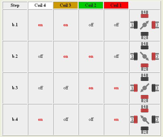
Note that in reality the coils have a north and south pole, and the rotor also has a north and south pole. The coils (in the picture) 1 and 3 are really the same one coil, and poles 2 and 4 are the other coil. Depending on current flow pole 1 is north and pole 3 is south, or vise-versa when the current flows the other way (same for ploes 2 and 4). This picture does not show this, they show on and off states on the 4 poles. Just make a mental check and set up the arbitrary reference that when a pole is "on" it is a north pole, when it is off it is south. And the rotor arrow symbol is always a south pole. Just do not confuse this with the current being on or off.
Anyway, looking at the code sequence above, the first one of 0 and 1 represents the step in the picture "b.2" - assign the first number to the "coil 4" column and the second number to the "coil 3" column. Next step is sequence 0 and 0, same as picture step b3. Next one is b.4, and finally back to b.1
To make the motor rotate the other way simply reverse the step sequence.
- Bruce
-
bluetrepidation
- Experienced Squirter
- Posts: 197
- Joined: Sun Nov 13, 2005 8:24 pm
- Location: Youngstown Ohio
OH! Please post.... Very interesting.
A.J.
A.J.
JSC wrote:I did some testing today, on my test setup my IAC motor ran perfectly at 7 VDC, had a few glitches at 6 volts, so unless the battery voltage is dropping below 7 volts when cranking, I don't believe voltage is a problem. I recorded the waveform at the phase inputs of the 2916 stepper driver on my MSII board and found something very interesting. The first step or maybe the first two steps in most movements are not phased correctly. This IMHO explains why, if the motor has to go somewhere (ie 100 steps) it seems to work (2 missed steps out of 100 = 2% error), but, if it has to go a few steps at a time it doesn't work ( two missed steps out of 4 = 50% error). In every instance when IAC1 from the CPU was low (0) and IAC2 from the CPU was hi (1), the next step was IAC1 (1), IAC2 (0). They both switch at the same time. I have waveforms to post, probably Monday, much easier on my work computer. The situation I'm seeing points to a programming issue.
Scott
1999 Saturn SC2 1.9L DOHC 4 cyl NA
MS II Blue Processor w/ 2.684 Beta Code
V3 PCB
MegaTune 2.25
Innovate LC1 WB O2 Sensor
OBD I Saturn Wasted Spark DIS
w/ Cooling Fan and IAC
MS II Blue Processor w/ 2.684 Beta Code
V3 PCB
MegaTune 2.25
Innovate LC1 WB O2 Sensor
OBD I Saturn Wasted Spark DIS
w/ Cooling Fan and IAC
One other thing that should be added to what Bruce said. You may ask why only two inputs are required to the stepper chip (the polarities of one end of the each coil) and it puts out 4 outputs. The chip automatically supplies the polarity of the other end of each coil as the opposite of the first, so that current is always flowing one way or another in each coil. This method produces the highest torque, but requires double the current. (As opposed to single coil excitation in which one coil is off while the other is on,) Both inputs to the stepper chip are supposed to go out of MS2 at the same time because you want the rotor to flip to the next 90 deg position..