Here is the VR circuit:
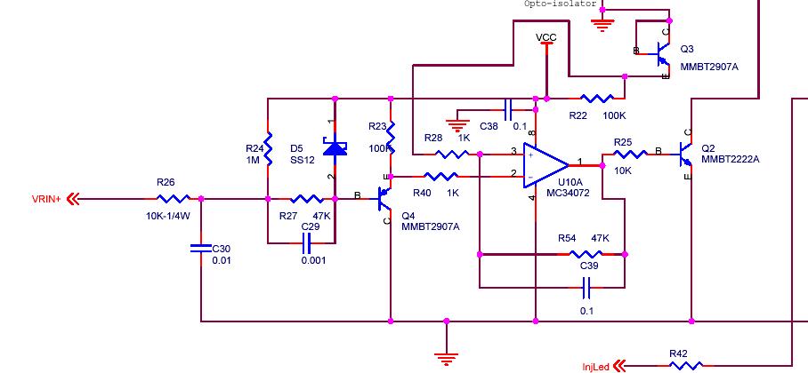
There is a diode D5 which is used to shunt the VR current whenever the VR voltage reaches a potential above the 5 volt rail (VCC). This is needed to protect the transistor Q4 from emitter-base reverse voltage, and it works just fine for this purpose.
When the VR potential is below the 5V rail the diode is back-biased and is turned off. The transistor Q4 is turned on as the VR potential drops thru zero and below, it stays conducting throughout the entire negative swing.
Here's the issue - the SS12 diode has a reverse voltage rating of 20 volts, kinda weak for this application. A VR sensor can produce as much as 100 volts or more at high RPMs. If the reverse voltage across this diode exceeds its breakdown it will avalanche and conduct, and this effectively shuts off the transistor. There is a voltage-divider arrangement with the diode amongst the resistors and transistor so the breakdown is not at 20 volts but higher, however it is indeed possible. On the other hand, the diode is referenced to the 5V rail, so in effect there is a -15 volt potential on the VR before breakdown (referenced to the VR- input)....
Also, when the breakdown occurs the diode heats up. This lowers the breakdown voltage so the effect occurs at lower voltages. This is the reason for the hot-start issues that some (including myself) have experienced.
So in order to correct this for people experiencing issues (not everybody will have this problem, it depends on the VR arrangement), the fix is to replace this diode with one with a better reverse voltage rating. I have used a thru-hole diode 1N4148 as a replacement - this is a 100V reverse voltage device. luckily, the diode D5 is easily replaced:
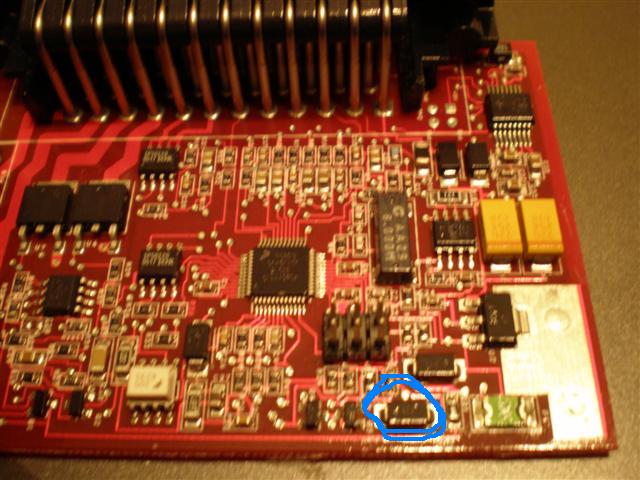
First, here is where D5 is located:
You need to remove this diode with a soldering iron. You can heat up one pad and lever the diode up in the air so that it is supported by the other pad, then apply the iron to the other pad to remove.
Next, bend the leads of the 1N4148 so that it fits on the pads. Make sure it does not hand off the edge of the PCB because this can short to the case. Then solder to the pads, adding a little solder. The band of the diode needs to point towards the green polyfuse device right next to it.
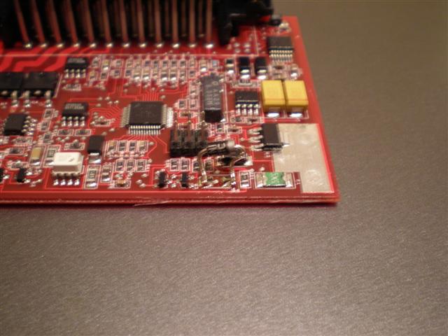
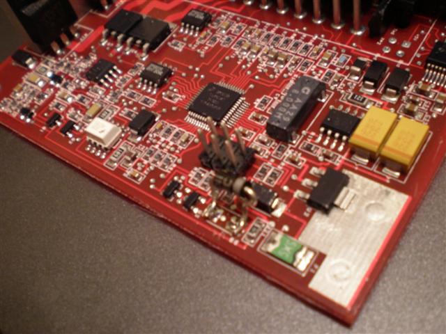
Here are photos of the mod:
You can use any diode with a 100V rating or above, like a 1N4004, etc. Also, if you do not feel comfortable performing this mod, send me a PM and I will help.
After performing this mod, you should be able to remove any external resistance on the VR line, since most likely it was added to prevent the diode from the reverse breakdown issue, which showed up as high RPM dropout. Also, all future MicroSquirt units shipped will have a diode with a high breakdown voltage.
- Bruce


