ideal cam and crank wheel for single cyl

Forum for discussing how to install MicroSquirt(TM), choose and troubleshoot sensors, wiring, and communications for MicroSquirt (TM) and MicroSquirt Module(TM).
Forum rules
Read the manual to see if your question is answered there before posting. If you have questions about MS1/Extra or MS2/Extra or other non-B&G code configuration or tuning, please post them at http://www.msextra.com The full forum rules are here: Forum Rules, be sure to read them all regularly.
sn95.ohh
Helpful Squirter
Posts: 43
Joined: Wed Aug 03, 2011 3:52 pm

Re: ideal cam and crank wheel for single cyl

Post by sn95.ohh »

mfro wrote:Don't think it really matters if the sensor is smaller than the tooth (as long as there is a clear signal). I think the manual advice rather meant you'll run into problems if the sensor is wider than the tooth since the MS will most likely see more than one tooth at a time with a multi-teeth wheel leading to problems.

KTM engine?
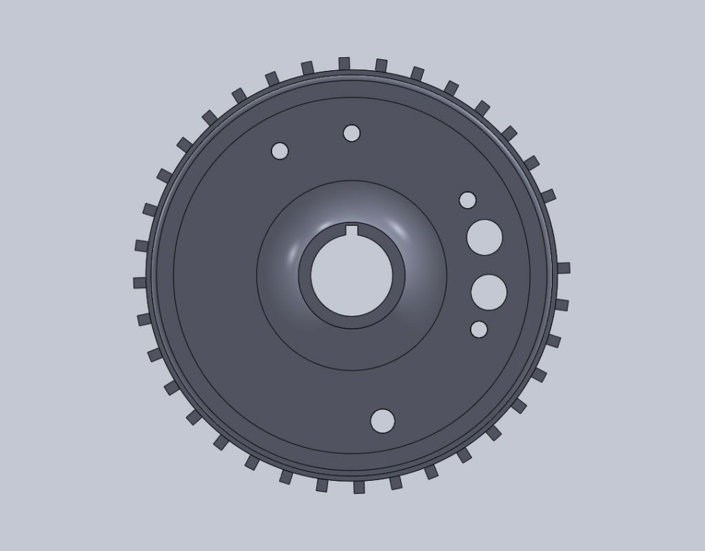
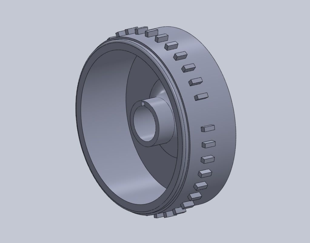
ok so your saying a little longer tooth would be fine.

Ya its a KTM. We have a 450sx that I will be doing testing on and then when it all runs smooth I will swap the setup over to a 560SMR. This is going in our Formula SAE car.
Formula SAE
RoadRunner Racing UT-San Antonio
www.roadrunner-sae.com
sn95.ohh
Helpful Squirter
Posts: 43
Joined: Wed Aug 03, 2011 3:52 pm

Re: ideal cam and crank wheel for single cyl

Post by sn95.ohh »

dontz125 wrote:A long tooth causes significant issues for the standard uS and MS VR hardware, as they are looking for the zero-crossing between the tooth edges. When the edges and the sensor are the same width, the zero-crossing happens pretty much at the same point every time. When the edges are a significant distance apart, the "zero-crossing" signal can happen at pretty much any time between those edges; when the tooth is 30 degrees wide, this is an intolerable error.

For a single long-tooth set-up like yours, I have to wonder if running your VR sensor to the OPTO input might not be the ticket - it will give you a single trigger pulse on the leading edge of the tooth (or trailing edge, if you hook it up backwards - not sure that it would particularly matter in this case).

Some people say that a single tooth isn't accurate enough - the OEM seemed to think so ... :lol:
How can the "zero-crossing" signal happen at anytime with a long tooth? If the sensor is over the tooth shouldnt the signal be constant?
Formula SAE
RoadRunner Racing UT-San Antonio
www.roadrunner-sae.com
dontz125
Master Squirter
Posts: 375
Joined: Mon Jun 29, 2009 1:00 pm
Contact:

Re: ideal cam and crank wheel for single cyl

Post by dontz125 »

Nope - that's how a Hall sensor works, but not a VR. A VR detects a CHANGE in magnetic field / metal presence; the Hall sensor detects the presence of a mag field (or metal if you're using a gear tooth sensor). The positive pulse of the VR sensor happens when the leading edge approaches / passes the sensor; the negative pulse happens when the trailing edge goes by. When the tooth and sensor are pretty much the same width, the positive and negative pulses blend smoothly one into the next, and the timing of the zero-crossing is very regular.

When the tooth is significantly longer, the voltage through the VR sensor drops to zero as the leading edge goes by, and then doesn't drop below zero until the trailing edge approaches. The problem then becomes one of noise; there is so much time (relatively speaking) between the edges that a noise pulse can get picked up and registered as a zero-crossing - and can happen at any time between the edges.

A multi-cylinder like a FZR or GSXR with its "1 long tooth and 3 short teeth" requires special handling; Matt_GSXR on the Extra site has done excellent work and is using a custom conditioner and modified code to read this commonly used (on motorcycles) wheel.

For a single tooth, all you need is something to identify the edge. The standard MS VR conditioner won't work, but the OPTO should do rather nicely.
sn95.ohh
Helpful Squirter
Posts: 43
Joined: Wed Aug 03, 2011 3:52 pm

Re: ideal cam and crank wheel for single cyl

Post by sn95.ohh »

dontz125 wrote:Nope - that's how a Hall sensor works, but not a VR. A VR detects a CHANGE in magnetic field / metal presence; the Hall sensor detects the presence of a mag field (or metal if you're using a gear tooth sensor). The positive pulse of the VR sensor happens when the leading edge approaches / passes the sensor; the negative pulse happens when the trailing edge goes by. When the tooth and sensor are pretty much the same width, the positive and negative pulses blend smoothly one into the next, and the timing of the zero-crossing is very regular.

When the tooth is significantly longer, the voltage through the VR sensor drops to zero as the leading edge goes by, and then doesn't drop below zero until the trailing edge approaches. The problem then becomes one of noise; there is so much time (relatively speaking) between the edges that a noise pulse can get picked up and registered as a zero-crossing - and can happen at any time between the edges.

A multi-cylinder like a FZR or GSXR with its "1 long tooth and 3 short teeth" requires special handling; Matt_GSXR on the Extra site has done excellent work and is using a custom conditioner and modified code to read this commonly used (on motorcycles) wheel.

For a single tooth, all you need is something to identify the edge. The standard MS VR conditioner won't work, but the OPTO should do rather nicely.
Ok I think I get it now. So with a hall sensor I can get away with a long tooth and be fine but with a VR sensor the tooth width should be the same as the sensor.

So now I have another question. Is the gap between teeth a big deal? Like is a big gap from one tooth to the next a bad thing??

Who would you recommend buying sensors from? I would like to get one with a bigger pickup so the teeth can be wider

Im sorry for asking so many questions but I want to make sure I get this right. You guys have been a big help. Thanks!
Formula SAE
RoadRunner Racing UT-San Antonio
www.roadrunner-sae.com
mfro
Helpful Squirter
Posts: 54
Joined: Mon Apr 13, 2009 10:13 am
Contact:

Re: ideal cam and crank wheel for single cyl

Post by mfro »

dontz125 wrote:Nope - that's how a Hall sensor works, but not a VR.
Don't want to doubt your statements but from my own practical experience, I can say I had a MS working pretty good on a (originally CDI ignited) Honda single with rather long single tooth and OEM sensor but had problems at first when I changed to a multi-tooth trigger wheel with a VR sensor which obviously was too wide.
sn95.ohh
Helpful Squirter
Posts: 43
Joined: Wed Aug 03, 2011 3:52 pm

Re: ideal cam and crank wheel for single cyl

Post by sn95.ohh »

Ok I want yalls opinion on something.

Here is how our current flywheel looks.
Image
Image
And this is what I wanted to do to it. I wanted to machine the pickup down and then machine teeth into the outter ring.
Image
Image


So here are a few questions.
1. I saw some where on a microsquirt site that the teeth needed 45 degree angles with a VR sensor. Is this true?? It would make it alot easier to machine if I didnt need the angles and just cut square teeth.

2. Where should I position the missing tooth?? I modeled it to where the VR sensor sits at the top of the first tooth after the missing tooth when the motor is at TDC. Is this correct?
Formula SAE
RoadRunner Racing UT-San Antonio
www.roadrunner-sae.com
24c
Master Squirter
Posts: 593
Joined: Sat Feb 16, 2008 12:15 pm
Location: Chorley, Lancashire UK
Contact:

Re: ideal cam and crank wheel for single cyl

Post by 24c »

You don't need angle teeth, as in my experience, you get higher voltages generated with sharper edges. However, you could also use axial circular pits by using say a 8mm 4 flute milling bit, which is what a lot of Yamaha engines used in the past on their crank webs.

Also another tip, the missing tooth needs to be in a area where the engine doesn't slow down too much under cranking AFAIK, so that the MicroSquirt can see this missing tooth, but where that is I wouldn't get too hung up on, because you have taper crank fitment, and you can just remove the keyway and position the flywheel anywhere.

EDIT. Just noticed your image has a parallel fitment. :)

On the other hand, somebody else with single cylinder experience (mine is multi) might chime in and give their best take based on their experiences to date.

PS From what I have read so far, the later software that is coming (3.760) will be a better suited to single cylinder engines
sn95.ohh
Helpful Squirter
Posts: 43
Joined: Wed Aug 03, 2011 3:52 pm

Re: ideal cam and crank wheel for single cyl

Post by sn95.ohh »

Ok ill make another model with no angles and more teeth then.

And the flywheel does have a taper fit I was just to lazy to model lol
Formula SAE
RoadRunner Racing UT-San Antonio
www.roadrunner-sae.com
sn95.ohh
Helpful Squirter
Posts: 43
Joined: Wed Aug 03, 2011 3:52 pm

Re: ideal cam and crank wheel for single cyl

Post by sn95.ohh »

I just read here: http://www.megamanual.com/ms2/pickups.htm that the ideal tooth is a right angle tooth so it ramps up slow then drops off fast. Has anyone done this??

Whats really the benefit of ramping up slow and dropping off fast??

EDIT: Nevermind I think I get it but if anyone would like to chime. Please feel free
Formula SAE
RoadRunner Racing UT-San Antonio
www.roadrunner-sae.com
sn95.ohh
Helpful Squirter
Posts: 43
Joined: Wed Aug 03, 2011 3:52 pm

Re: ideal cam and crank wheel for single cyl

Post by sn95.ohh »

ok here is what I came up with. I think this will work perfect. What do yall think?

36-1
Image
Image
Formula SAE
RoadRunner Racing UT-San Antonio
www.roadrunner-sae.com
Post Reply