Its the same as the GM sensor, so it should work fine.. it is found on most holdens from that era not just the VS/VTsidy wrote:I agree...
On the subject of MAP sensors, would any from Australian model VS/VT
etc commodores be suitable ?
Sid
Posted by email.
MicroSquirt
Forum rules
Read the manual to see if your question is answered there before posting. If you have questions about MS1/Extra or MS2/Extra or other non-B&G code configuration or tuning, please post them at http://www.msextra.com The full forum rules are here: Forum Rules, be sure to read them all regularly.
Read the manual to see if your question is answered there before posting. If you have questions about MS1/Extra or MS2/Extra or other non-B&G code configuration or tuning, please post them at http://www.msextra.com The full forum rules are here: Forum Rules, be sure to read them all regularly.
Re: MicroSquirt
If it is not too late, I would like to suggest that the power ground and the signal ground be seperated and come out at different pins on the connector. The user can then connect the two together at one point on the chassis for a cleaner sensor signal.
Last edited by woh on Tue Jan 31, 2006 12:27 pm, edited 1 time in total.
-
leealley2001
- MegaSquirt Newbie
- Posts: 5
- Joined: Sun Jan 09, 2005 12:49 pm
- Location: Arizona
-
leealley2001
- MegaSquirt Newbie
- Posts: 5
- Joined: Sun Jan 09, 2005 12:49 pm
- Location: Arizona
-
Bernard Fife
- Super Squirter
- Posts: 1009
- Joined: Mon Feb 16, 2004 3:15 pm
leealley2001,
The VR input circuit on MicroSquirt is completely different from the V3 main board VR input circuit. It is based on Bruce's EasyVR zero-crossing detector circuit. (This circuit is also used on the GPIO board.)
Bruce says,
http://www.msefi.com/viewtopic.php?t=9142
Lance.
The VR input circuit on MicroSquirt is completely different from the V3 main board VR input circuit. It is based on Bruce's EasyVR zero-crossing detector circuit. (This circuit is also used on the GPIO board.)
Bruce says,
There's more here:Also, if you are eperimenting with VR circuits, I have been having really good results with the circuit I posted at http://www.msefi.com/viewtopic.php?t=9142 . It is so simple to make and it yields real good results.
http://www.msefi.com/viewtopic.php?t=9142
Lance.
-
leealley2001
- MegaSquirt Newbie
- Posts: 5
- Joined: Sun Jan 09, 2005 12:49 pm
- Location: Arizona
Oops, I assumed the VR circuit was the same based on Bruce's comment "The circuitry is pretty much the same as the V3/MSII, with the exception of the injector drivers." as found here: http://www.msefi.com/viewtopic.php?t=15044
You know what they say about assumptions
Thanks for setting me straight Lance.
You know what they say about assumptions
Thanks for setting me straight Lance.
-
Bernard Fife
- Super Squirter
- Posts: 1009
- Joined: Mon Feb 16, 2004 3:15 pm
Does anyone have dimensional data for the case to be used for MicroSquirt??
Ideally I would like to know internal dimensions and how much space is available with MicroSquirt installed.
It would be helpful to see a pic of the case with a MicroSquirt board on the info site, together with the dimensions.
Ideally I would like to know internal dimensions and how much space is available with MicroSquirt installed.
It would be helpful to see a pic of the case with a MicroSquirt board on the info site, together with the dimensions.
-
Bruce Bowling
- Site Admin
- Posts: 285
- Joined: Mon Feb 16, 2004 4:25 pm
- Location: Baltimore, MD
In fact, I took some photos of the latest board. Here are the exact dimensions:aarc240 wrote:Does anyone have dimensional data for the case to be used for MicroSquirt??
Ideally I would like to know internal dimensions and how much space is available with MicroSquirt installed.
It would be helpful to see a pic of the case with a MicroSquirt board on the info site, together with the dimensions.
Case Length (end plate to end plate, not including flange): 2.75"
Case Length (end plate to end plate, including flanges): 3.75"
Case width: 3.73"
Case Height: 1.70"
Pictures:
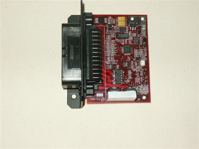

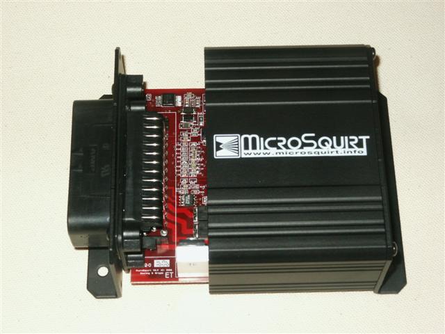
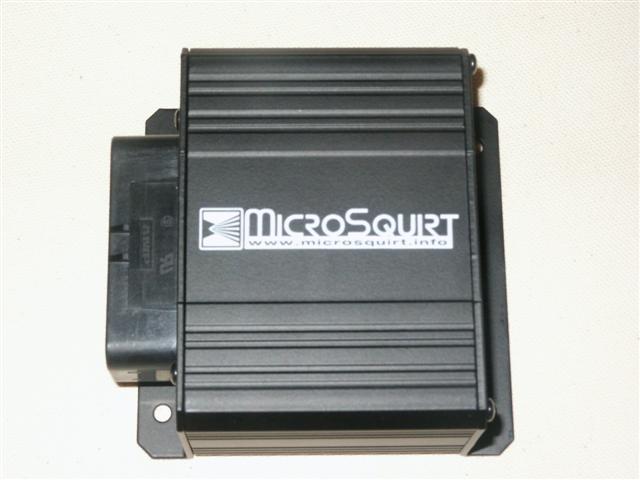
As far as the testing, the power, inputs, and FI outputs are tested. I am now in the process of checking the ignition driver channels. So far so good! Also, the unit will be tested on 3 different vehicles next week. If the tests go O.K., I can turn on a panel run of boards within a week or so. It then takes about a month to get them completed.
- Bruce
-
boost junkie
- Helpful Squirter
- Posts: 62
- Joined: Tue May 11, 2004 7:58 am
- Location: dallas texas usa