Page 3 of 5
Re: MicroSquirt
Posted: Sat Jan 21, 2006 7:41 pm
by rs2000
sidy wrote:I agree...
On the subject of MAP sensors, would any from Australian model VS/VT
etc commodores be suitable ?
Sid
Posted by email.
Its the same as the GM sensor, so it should work fine.. it is found on most holdens from that era not just the VS/VT
Posted: Fri Jan 27, 2006 4:31 pm
by woh
If it is not too late, I would like to suggest that the power ground and the signal ground be seperated and come out at different pins on the connector. The user can then connect the two together at one point on the chassis for a cleaner sensor signal.
Posted: Tue Jan 31, 2006 9:41 am
by leealley2001
From what I can tell, the VR circuit in the microsquirt is the same circuit as on the V3.0 board. This leads me to the question; How were the potentiometers in the VR circuit eliminated on the microsquirt? How is the zero crossing point adjusted without them?
Posted: Fri Feb 03, 2006 9:06 am
by leealley2001
HMM, lots of reads.
Is the question unclear the way I stated it?
Such a good question nobody knows the answer?
Such a dumb question nobody is going to bother?
Posted: Fri Feb 03, 2006 10:01 am
by Bernard Fife
leealley2001,
The VR input circuit on MicroSquirt is completely different from the V3 main board VR input circuit. It is based on Bruce's EasyVR zero-crossing detector circuit.
(This circuit is also used on the GPIO board.)
Bruce says,
Also, if you are eperimenting with VR circuits, I have been having really good results with the circuit I posted at
http://www.msefi.com/viewtopic.php?t=9142 . It is so simple to make and it yields real good results.
There's more here:
http://www.msefi.com/viewtopic.php?t=9142
Lance.
Posted: Fri Feb 03, 2006 11:36 am
by leealley2001
Oops, I assumed the VR circuit was the same based on Bruce's comment "The circuitry is pretty much the same as the V3/MSII, with the exception of the injector drivers." as found here:
http://www.msefi.com/viewtopic.php?t=15044
You know what they say about assumptions

Thanks for setting me straight Lance.
Posted: Fri Feb 03, 2006 11:43 am
by Bernard Fife
leealley2001,
Actually, thanks to you for bringing it up, I'll fix the docs right now!
Lance.
Posted: Sat May 20, 2006 2:34 am
by aarc240
Does anyone have dimensional data for the case to be used for MicroSquirt??
Ideally I would like to know internal dimensions and how much space is available with MicroSquirt installed.
It would be helpful to see a pic of the case with a MicroSquirt board on the info site, together with the dimensions.
Posted: Sat May 20, 2006 11:25 am
by Bruce Bowling
aarc240 wrote:Does anyone have dimensional data for the case to be used for MicroSquirt??
Ideally I would like to know internal dimensions and how much space is available with MicroSquirt installed.
It would be helpful to see a pic of the case with a MicroSquirt board on the info site, together with the dimensions.
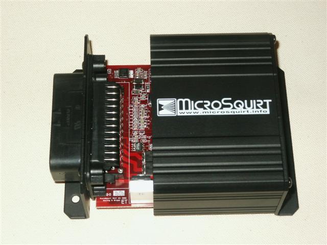
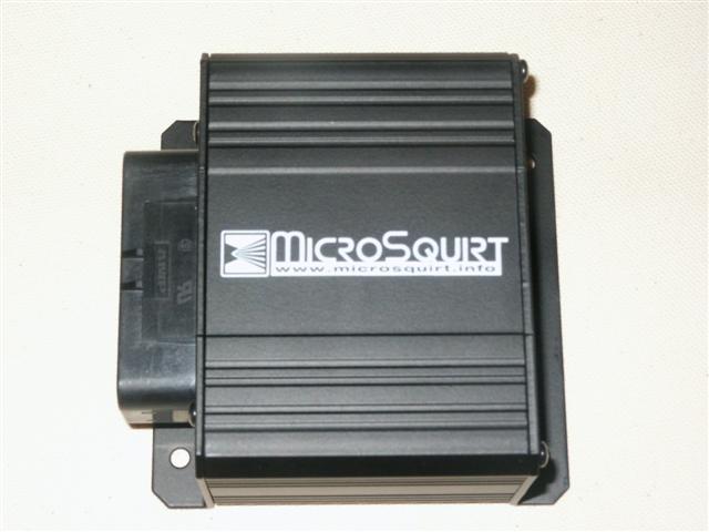
In fact, I took some photos of the latest board. Here are the exact dimensions:
Case Length (end plate to end plate, not including flange): 2.75"
Case Length (end plate to end plate, including flanges): 3.75"
Case width: 3.73"
Case Height: 1.70"
Pictures:
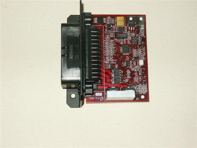

As far as the testing, the power, inputs, and FI outputs are tested. I am now in the process of checking the ignition driver channels. So far so good! Also, the unit will be tested on 3 different vehicles next week. If the tests go O.K., I can turn on a panel run of boards within a week or so. It then takes about a month to get them completed.
- Bruce
Posted: Sat May 20, 2006 12:12 pm
by boost junkie
All I can say is WOW. That looks great!