So, how many teeth do I really need?

This forum is for discussing ignition setup, tuning, and troubleshooting for MicroSquirt (TM)
Forum rules
Read the manual to see if your question is answered there before posting. If you have questions about MS1/Extra or MS2/Extra or other non-B&G code configuration or tuning, please post them at http://www.msextra.com The full forum rules are here: Forum Rules, be sure to read them all regularly.
24c
Master Squirter
Posts: 593
Joined: Sat Feb 16, 2008 12:15 pm
Location: Chorley, Lancashire UK
Contact:

Re: So, how many teeth do I really need?

Post by 24c »

Drawing came in the mail, thanks Greg...converted the jumpers to Logic Level Outputs, wired up the Dyn-Evo Ignition Amp as per spec, skinny wires paired to IGN1 & IGN2, fat wires paired to the dummy coils (LEDs), prewired 12V+ and fat black to ground.

Cranked the rig, and bingo LEDs alternating, so I now have MicroSquirt V2 running LLO, 4 COPs wasted spark in theory.
d1c3_2.JPG
d1c3_2.JPG (6.26 KiB) Viewed 1318 times
ebay links not permitted - Admin
The reason I chose this item, was it has long leads and I can wire it into the R6 COPs without blowing loads of pennies on connectors. 8)
24c
Master Squirter
Posts: 593
Joined: Sat Feb 16, 2008 12:15 pm
Location: Chorley, Lancashire UK
Contact:

Re: So, how many teeth do I really need?

Post by 24c »

Don't know whether I should start another thread, but leading on from the other page..

I am trying to get the GTS1000 running, it's got 4 'teeth' on a crank wheel and a 1 'tooth' cam lobe, for VR2+.
rev_pol_runningGTS.png
rev_pol_runningGTS.png (45.46 KiB) Viewed 1246 times
I can get cranking tach on the drill powered rig, from about 120 rpms upward, and by this I mean I can see the tachometer working in TunerStudio or MegaTune. However on the bike, I've got nothing.

I can see the processed pulses using the TachRef.exe program when I piggyback the VR signals off an idling engine running off the original ECU...and occasionally I can see cam and crank sensor square waves on the same screen (blue and yellow plot above), but most times I only see the crank plot, although the cam sensor is working.

I have wired the cam sensor into the crank VR1 inputs and I see a nice regular plot, yet it doesn't show on the VR2 plot. I have tried switching polarity and there is no difference in behaviour, other than the crank plot "inverts".

Does anybody have experience of this, or can you change the sensitivity of the VR circuits easily on the MicroSquirt..as I understand the MegaSquirt had some pots you could alter.

PS I really don't know why I'm getting that unusual tooth pattern, they should all be the same width, unless there is a crankshaft oil plug very close on this engine.
24c
Master Squirter
Posts: 593
Joined: Sat Feb 16, 2008 12:15 pm
Location: Chorley, Lancashire UK
Contact:

Re: So, how many teeth do I really need?

Post by 24c »

Had another play today, hooked up the scope, and got a nice & typical VR cam sensor trace. The crank sensor has a lot of spiky AC noise on it, and it drowns the cam sensor trace on my software scope, yet the µS reads RPMs from 1400, so it can't be an issue..can it?

Piggybacking the Microsquirt VR1 & VR2 inputs onto the engine, and starting the bike with the factory ECU, I get no cranking rpms, however the RPMs do start to move from 1400 upwards in TunerStudio or MegaTune, and they are indicating the right speed now (cylinders were 8 not 4) :oops:

I varied the Base Ignition Settings, to try and get a lower rpm start up, but other than a polarity reverse, that made the ±triggers more stable, and stay at 0, except when snapping the throttle quickly, where it lost the odd one.

I zeroed all the Tach Signal Masking and the Next-Pulse Tolerances, and I got no rpms. As I wasn't detecting cranking or after start at idle, I played with the Next Pulse Tolerance settings, blipping and holding the throttle from 1400 upwards, and kept watching the ±trigger count, it stabilised after Normal Running was 30-35%.
grippo
MegaSquirt Guru
Posts: 921
Joined: Mon Feb 16, 2004 6:55 pm

Re: So, how many teeth do I really need?

Post by grippo »

Several things. In your tachref plot, what counts is the spacing between the EDGEs being close to the same. For example, if you measure the distances of the crank teeth edges, then if you choose falling edge, the wide tooth won't hurt anything, but if you choose rising edge it will.

In dual spark the masks have no effect. The pulse tolerances can not be set to 0 - that asking that everything be absolutely perfect. Leave them as the defaults until you get to the stage where yopu are just getting minor misses.

A 4 tooth wheel should work, but it gives horrible accuracy. It is fine with a distributor, because the dizzy takes care of the fine timing. I would want something with at least 12 teeth.
24c
Master Squirter
Posts: 593
Joined: Sat Feb 16, 2008 12:15 pm
Location: Chorley, Lancashire UK
Contact:

Re: So, how many teeth do I really need?

Post by 24c »

grippo wrote:..For example, if you measure the distances of the crank teeth edges, then if you choose falling edge, the wide tooth won't hurt anything, but if you choose rising edge it will.
I have been reading some more re. MS2/Extra tooth noise post, and after your post I know understand what rising and falling edges mean..finally! My configuration is rising edge for the crank trigger :oops: :oops:
grippo wrote:A 4 tooth wheel should work, but it gives horrible accuracy...snip ... I would want something with at least 12 teeth.
4 "teeth" work on the bike already, but I note your comments, and if I could change it easily I would, but unfortunately the engine doesn't have a removable crankcase cover like most, it's a horizontal split design.

Thanks for your post, I will have another go tomorrow, using falling edges.
24c
Master Squirter
Posts: 593
Joined: Sat Feb 16, 2008 12:15 pm
Location: Chorley, Lancashire UK
Contact:

Re: So, how many teeth do I really need?

Post by 24c »

Hi again, another day, and the falling edges for the "ignition capture" did mean I got RPMs seen from 700 onwards briefly, before being stable at 1300 or so, but bear in mind the engine is idling at 1000 rpm or thereabouts, so this first figure must be the gauge catching up. :) It now only skips a ±trigger evry now and again at 4000 rpm 8)

I still can't see cranking RPM, with pulse tolerances at default, and under investigation using TachRef.exe, on a running engine I don't seem to get a cam sensor plot. After what Al posted about seeing edges, I can only assume the Microsquirt can't see any on the VR2 input. To double check this, I cranked the engine with the cam sensor VR2 unplugged and there was no difference, slight bit of false instantaneous edging on the crank VR1 plot, but the falling edges look OK. I again assume that these instantaneous edges the thickness of a line would be covered in the pulse tolerance settings, so they are ignored?
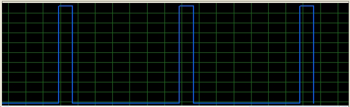
cam_on_vr1.jpg
cam_on_vr1.jpg (81.34 KiB) Viewed 1198 times
I know I have a good quality VR signal, as I have seen it on my USB oscilloscope, and it has a steep climb, so the Microsquirt should be able to process this info. However, the interesting thing is if I plug the cam sensor VR into the VR1 crank inputs, I get a healthy plot in TachRef straightaway on ceasing cranking (with either polarity). So it looks like I have a faulty VR2 connection/input, because AFAIK the MicroSquirt is not seeing anything on this input...at cranking. It does later, on a running engine going fast idle at 1400 onwards. :? :?

I did have an early loom with the wiring/pin mismatch, but this has been switched. I am going back outside to check continuity from the MicroSquirt pcb to the VR2 loom.

UPDATE I have checked the loom continuity from the cam sensor to the underside of the MicroSquirt pcb, to where the Ampseal connector is soldered to the board. After some probing to get through the conformal coating, I got continuity. :shock: I was hoping I wouldn't.

This is so frustrating, as I am at a loss to understand what is happening, other than it looks like intermittent VR2+ signal processing at the MicroSquirt is the issue. I am assuming that if TachRef can't see it on the VR2+ input, then the MicroSquirt can't either :?
Anybody got any proper suggestions please.
24c
Master Squirter
Posts: 593
Joined: Sat Feb 16, 2008 12:15 pm
Location: Chorley, Lancashire UK
Contact:

Re: So, how many teeth do I really need?

Post by 24c »

So a follow on...I did manage to get the rpms to display, from 900 revs onwards. Couldn't do anymore today, as USBSerial stopped talking to MicroSquirt. Permanently offline in TunerStudio, in Windows XP or OSX 10.5 and wouldn't go online. :? :x

Hooking up the USB oscilloscope beforehand trying to understand what is happening, got me these traces on cranking and on idle.
OSCcrankGTS.jpg
OSCcrankGTS.jpg (78.74 KiB) Viewed 1195 times
osc_runGTSidle.jpg
osc_runGTSidle.jpg (83.42 KiB) Viewed 1194 times
24c
Master Squirter
Posts: 593
Joined: Sat Feb 16, 2008 12:15 pm
Location: Chorley, Lancashire UK
Contact:

Re: So, how many teeth do I really need?

Post by 24c »

Sorry about the truncated posting, but my broadband is down every 30 seconds or so atm. I live in the sticks, so it's slow as well, and the only way to post an update was to do it in smaller parcels. :)

Is the VR2 circuit less sensitive than VR1, because as the revs climb the peak to peak voltage on the cam sensor improves, and it looks like I'm only managing 100mV peak to peak on cranking. Is this enough? The crank sensor generates far more p-pV.

To increase the generated p-p voltage, I would have to file down the cam cover to decrease the clearance between the sensor and the cam lobe. Another way, I could use a conditioning board, convert it to a square wave and use the OPTO inputs?

Ordered two from jbperf.com

Is there anything else folks can suggest, other than arson :wink:
Post Reply