Page 1 of 1

VB921 on V2.2

Posted: Tue Sep 12, 2006 9:48 am
by AriK
I kind of asked this already on another topic in another forum here, but I'm not sure if people will find it there ;). So I apologize for "multiposting" this...

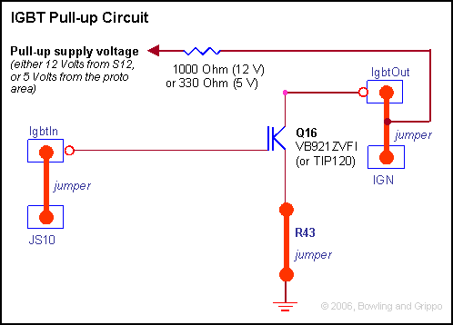
The idea is to put a VB921 driver inside a broken ignitionmodule that is bolted on the coil. That way I can connect the coil and amp as before. Is it ok if I connect it like this:

Setup is v2.2 pcb with 029t MSnS-E.

Code: Select all

                                    +12v (fuel relay)
+-------------------+                o     +----------------------------+
| MS                |                |     |        +--------------o 15 |      
|                   |                |     |        |   1k              |
|                   |                o-----|--------+--/\/\--+          |
|            R25    |         wire         |                 |          |
|Pin7 o-----/\/\----|--o X12 <---->  o-----|-----+    /------+-----o 1  |
|            1k     |                      |     +--|| VB 921           |
|                   |                o-----|--+       \                 |
|                   |                |     |  +--------+                |
+-------------------+                o     +----------------------------+
                                    gnd     Module + coil
Hope the ASCII art is clear enough ;).

Re: VB921 on V2.2

Posted: Tue Sep 12, 2006 4:16 pm
by lumpensack2003
AriK wrote: Is it ok if I connect it like this:
AriK,
what is the 1K resistor for?
The one between terminal 15 and terminal 1 in the module.

Cheers

Posted: Wed Sep 13, 2006 6:59 am
by AriK
The 1k is from this picture, but seems to be irrelevant to this setup:

Image

So, about this schematic (extra):

Image

So, I took off the wrong 1k res. and fitted a 330ohm like the extra manual is telling. Is this ok? I also removed the R25 res from the schematic. That is what the extra manual is telling to solder the wire to RHS (right-hand-side), which is the processor side, right?

Code: Select all

                                    +12v (fuel relay)
+-------------------+                o     +----------------------------+
| MS                |                |     |        +--------------o 15 |     
|                   |                |     |        |                   |
|                   |                o-----|--------+                   |
|                   |         wire         |  330       +-----------o 1 |
|Pin7 o-------------|--o X12 <---->  o-----|-/\/\-+    /                |
|                   |                      |      +--|| VB 921          |
|                   |                o-----|--+        \                |
|                   |                |     |  +---------+               |
+-------------------+                o     +----------------------------+
                                    gnd     Module + coil 
Thanks lumpensack2003, for clearing out the pullup for me!

Posted: Wed Sep 13, 2006 11:31 am
by jsmcortina
I would suggest fitting the 330R inside the MS box so that if you get a short circuit between the Megasquirt and external box you won't destroy the CPU.

James

Posted: Thu Sep 14, 2006 3:09 am
by AriK
Thanks, jsmcortina!

I just swap the R25 to a 330ohm resistor and jumper it to the X12 output. That should do it.

What kind of dwell and discharge times the VB921 can handle? Any other changes than inverting the output?

Posted: Thu Sep 14, 2006 4:05 am
by jsmcortina
The dwell time is dependant on the coil, not the VB921.
However, if the VB921 is getting warm/hot then the dwell is too long. If it is too hot to touch then switch off the power right away.

James

Posted: Thu Sep 14, 2006 10:58 am
by AriK
Of course, a dumb question ;). Anyway, do you (or anyone) remember a setup for a scope to measure the inductance of a coil? This way I could calculate the estimate...