Page 1 of 1
For those running MSI with the Toyota VAST Ignition...
Posted: Wed Sep 13, 2006 6:12 pm
by ESB
I have an MSI with V3 main board and I know that in order for MS and the VAST ignition to communicate, you have to solder in resisitors.
However, I don't know where exactly and how to install these resistors, so if anyone would be willing to share pics or any knowledge, that would be much appreciated!!
Posted: Thu Sep 14, 2006 12:44 pm
by dcg9381
Which toyota motor do you have? (I'm just curious, it doesn't make a difference as long as you're using VAST)
If you have zero (and I mean zero) electronics / soldering experience, you'll want to find someone who can help you. Soldering is easy, but it's also easy to mess up the board and it's good to have someone show you how to do it to get started.
Here's a decent write up on it:
http://www.diyautotune.com/tech_article ... ta_mr2.htm
Generally if you don't hear a response to your questions on one of these forums, you haven't done your "due dilligence" / search / RTFM.
More information:
"There are a large number of cryptic designations in building a MegaSquirt. Many of these have the form of a capital letter followed by a one or two digit number. These indicate components that are installed on the MegaSquirt main board (or stim, etc.) and are specific to each PCB. So R9 means resistor (R) number 9. Note that the main board has a R9, as does the stim, and they are different. "
This will give you an idea of what you're looking for:
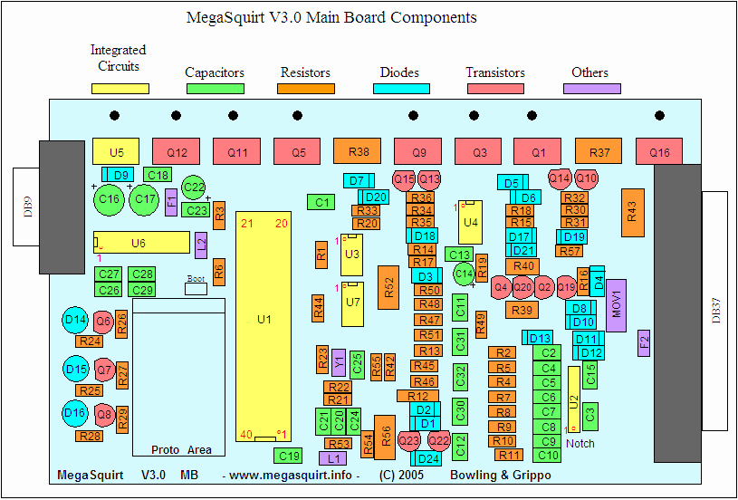
For the ignition input:
We need a 12v pullup. Install a 1k resistor between the right side (non-band) end of D1 and the left leg (banded end) of D9.
For the ignition output on LED14/Pin36:
First we need to bring the ignition output from LED14 out to a pin on the DB37. To do this run a small piece of hookup wire from LED D14's leg that's closest to the DB9, over to the hole labeled IGN at the opposite end of the board. This will bring the ignition signal out on pin 36, MS-II style.
Now we need a 5v pullup to this wire we just ran. That's easy on the v3 PCB as there are two 5v sources just above the proto area labeled +5v. Use a 1k resistor from one of these +5v holes either to the wire itself, or by tapping another piece of wire onto this resistor and running it over to IGN as well. (You could just tap it onto D14 as well, but it might be a little crowded there....your call)