Page 1 of 1

MicroSquirt Board Revision - Sept 2008

Posted: Sat Aug 30, 2008 6:19 pm
by Bruce Bowling
I wanted to share the changes that were introduced to the latest version of MicroSquirt (V2). The changes were all minor in nature and are enhancements to the version 1 board:

- Added series resistance to the Bootloader signal wire for added protection. In the version 1 board, the bootloader, if left unterminated, could lock the controller in a constant bootload mode. Note that, even with this modification, it is still recommended to terminate the bootloader wire to Vref (5 volts) when not in use.

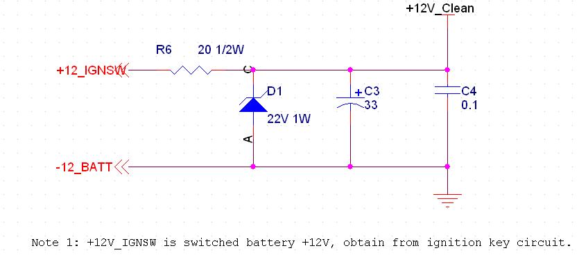
- Added overvoltage zener and series polyfuse to Vref line. This should help with inadvertent shorts of the Vref to +12V - but its no guarantee.... in other words protect the Vref from shorts to ground or +12V

- Changed D5 diode to a higher reverse voltage rating device (see sticky on this mod).

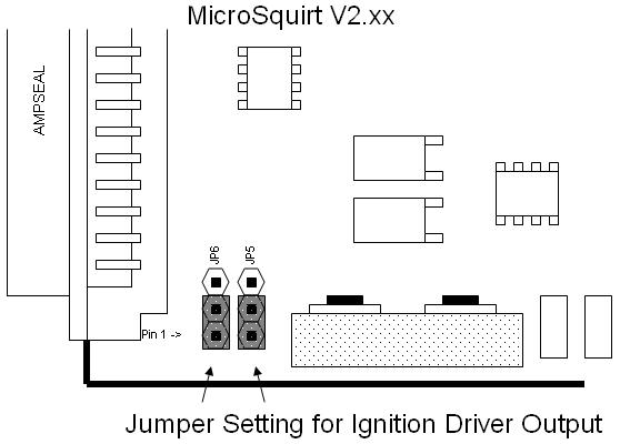
- Added jumper options for ignition output - the ignition outputs can be strapped for either logic-level output or direct driver outputs. There are two 3-position headers with a shorting jumper which is used to select the mode.

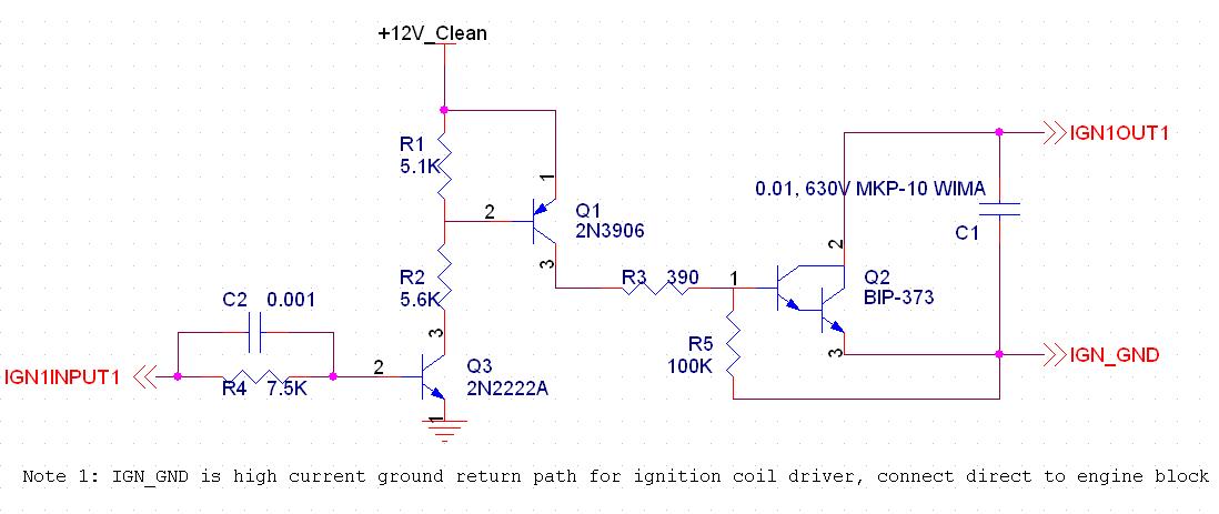
- Changed the VB921 to the Bosch BIP-373 device for the ignition driver stage. The BIP-373 is much more rugged and will shutdown on overtemperature. The older VB921 would often fail on overtemp conditions.

- Changed the PCB mask color from red (v1) to black (v2), in order to be able to easily tell the versions apart.

I have been testing the V2 version of the board on a small-block Chevy for the last few weeks and I am happy on the results. I have MicroSquirt running fuel (8 high impedance injectors) and driving the HEI ignition coil direct with the two BIP-373 in a wired-OR configuration under dual-spark.

MicroSquirts have been on backorder for a few months, this was due to the change in the PCB and lots of testing. We are now ready to release the new version. We have a bunch made up at the Contract Manufacturer and they are being finalized this week. So, MicroSquirt should be available from dealers in the next few weeks.

- Bruce

Re: MicroSquirt Board Revision - Sept 2008

Posted: Tue Sep 02, 2008 4:06 pm
by Bruce Bowling
I forgot to add one more option that is on the V2 version of MicroSquirt:

- The spare ADC channel AD7 is grought out on the ampseal. This means that there are two ADC channels available. Also, on this same pin, timer port 7 is also brought out and is shared with this input. This was done for Mass Air Sensor support. The new channel is designed for MAF sensors, either voltage-output or frequency-output types.

- Bruce

Re: MicroSquirt Board Revision - Sept 2008

Posted: Wed Sep 17, 2008 8:40 am
by Bruce Bowling
I wanted to elaborate a bit on the ignition driver setup on the V2 version of microsquirt, since this is the major part of the change from V1 to V2.....

On the V2 MicroSquirt, there is a jumper selection for ignition channel electrical output. There is a driver on the MicroSquirt, the BIP-373, which can drive an ignition coil directly. The BIP-373 is a real upgrade to the VB921 drivers that were used on the original MicroSquirt V1 board. The biggest improvement is a thermal shutdown capability that will self-protect the driver in case of overtemperature. The older VB921 did not have this, and would simply self-destruct due to the heat from overcurrent limiting. Also, the BIP373 has a higher flyback voltage (350V compared to 300V), and a current limit of around 12 amps (peak depends on ignition coil used and its resistance), compared to the 7 amps of the VB921. When the current limit is reached, the device will dump the excess voltage as heat in the driver, so the higher current limit headroom of the BIP-373 is good thing, and chances are the 12A limit will not be reached depending on dwell and ignition coil inductance.

The BIP-373 driver works well in the MicroSquirt. However, it can be a bit of a challenge to get working on some installations. The reason is that the ignition driver circuit has to handle lots of current (up to 12 amps per channel, and there are two channels). Also, the flyback pulse on the ignition driver can reach 350 volts during discharge, and this can cause all sorts of pulse noise havoc to the rest of the system. This is one big reason why most OEM installations separate the ignition drivers (a.k.a. ignitors) from the ECM, it really improves signal integrity for the rest of the system. FInally, the BIP-373 can only handle one coil (do not attempt to hook up more than one coil per driver) and many installs want to drive two coils per channel to maintain a COP arrangement for a 4 cylinder.

With this in mind, we strongly recommend that your installation uses an external ignition driver setup, and that you configure the MicroSquirt for logic-level output mode. What this means is that the MicroSquirt will provide a 0-5 volt signal output of low current which is then used to trigger an external driver module. The MicroSquirt documentation outlines several driver modules that can be used and how to hook them up. You can also use external BIP-373 drivers on your own board to drive the coils. I personally like to use the new ignition coils with the built-in ignitiors, they work great and really make the installation robust and easy. Also, setups using EDIS, etc will benefit from the logic-level mode as well.

With the V2 MicroSquirt, setting the unit up for logic level output is easy. There are jumpers on the board that configure this output between driver and logic output mode. The default factory position is BIP-373 driver output mode, it is set this way to test the drivers before shipping. To change the output mode to highly-desirable logic-level, remove the screws from the case and slide the MicroSquirt PCB out of the case. Hold the PCB with the ampseal pointing to the left and the silver heatsink along the bottom. The jumpers are on the lower left of the board near the edge, right next to the ampseal connector and the silver heatsink. Connect the jumpers as the diagram below for logic-level output (first image is for the on-board drivers, the second is the preferred logic-level output mode):

Image

Image
The logic level outputs can drive a few milliamps and are overvoltage protected, so they are pretty rugged, but be a bit careful on what you hook up to these.

If you still want to experiment with the on-board drivers (after all of the warnings here), then realize that the drivers can produce a lot of noise. I recommend pulling the ignition output wires out of the MicroSquirt harness and keep them separated from the rest of the bundle of wires. Remember the 350 volt pulse can easily couple back into the rest of the circuit just by having the wires in close proximity. If you get tach noise, sensor signal bouncing, serial link problems with the laptop, etc, then you need to separate these more. Also, grounding is extremely important, the 12 amps flows on the ground wire from the MicroSquirt. Any sort of voltage drops, etc will affect the rest of the circuit. Be sure that the high current grounds are connected to the engine block, and the sensor return wires are used for the sensors. Some installations go real smooth, but others can be a problem. Just try to keep the high current wires away from everything else. Remember that MicroSquirt has a lot of stuff crammed in a tiny package. You can get the drivers to work (right now I have both of the BIP-373s driving a single high-current coil in dual-spark mode on a SBC in a wired-OR configuration), just be mindful of the install.

Again, you can get the on-board drivers to work, but if you want a rock-solid install with minimal problems using the logic level output mode with external drivers is the way to go.

- Bruce

Re: MicroSquirt Board Revision - Sept 2008

Posted: Wed Sep 17, 2008 9:40 am
by Bruce Bowling
For those who want to build up a "DIY-style" ignition coil driver, the BIP-373 is an excellent choice. In order to extract the most out of the driver it is important to provide sufficient gate drive. The thing to watch out for is that the driver itself has a pretty hefty voltage drop from its base to emitter, Vbe is spec-ed to around 4.8 volts at 7 amps of current. This makes it hard to drive the BIP-373 to saturation from a logic-level output. So, a little buffering works well. Here is a circuit to try (image may show up cropped, right click and select "view image"):

Image

The BIP-373 is basically a Darlington (actually, its has another gain stage as well), so in order to provide sufficient voltage to the base a PNP transistor Q1 is used. Q2 is an inversion stage to keep the signal chain polarity correct. C2 is a speedup capacitor to make sure Q1 switches quickly.

There is a 0.01uf Polypropylene capacitor on the BIP-373 collector to ground. This helps shunt high frequency noise and keeps the circuit clean from a RFI perspective. Use a Wima type if possible.

This circuit is for one ignition coil, repeat for each COP coil. You can tie the inputs together if you need to fire coils at the same time - one logic level output from MicroSquirt can fire several of these driver circuits.

Here is a clean power circuit that you can use to drive the circuit, it will power many channels:

Image

The circuit has the added bonus - if the power comes from the vehicle ignition switch then it will only be active when the key is on. Its another level of protection for the ignition coils...

- Bruce

Re: MicroSquirt Board Revision - Sept 2008

Posted: Sat Oct 18, 2008 2:56 am
by vmaxmitch
Bruce, I've purchased one of the first units, but haven't been able to install it yet.... Do I have to update anything or will it work ok as is?

Thanks for your support and the huge information that is available on this site. Cheers, Mitch.

Re: MicroSquirt Board Revision - Sept 2008

Posted: Thu Nov 12, 2009 10:13 pm
by speedy6963
Bruce Bowling wrote:I wanted to share the changes that were introduced to the latest version of MicroSquirt (V2). The changes were all minor in nature and are enhancements to the version 1 board:
- Bruce

Question about the VR1 circuit on a v1 microsquirt, am i correct that it does not have C39? ( I cant find it, is shown in the schematics online (V2) )

Also am I correct that replacing Q3 with a 100k resistor and removing R54 should make the VR1 circuit function identical to VR2..

Thanks
John Cozad
Owner
Rev Hard Inc.

Re: MicroSquirt Board Revision - Sept 2008

Posted: Mon Aug 13, 2012 1:56 am
by Mhm
Bruce Bowling wrote: Image

Here is a clean power circuit that you can use to drive the circuit, it will power many channels:

Image
I'd like to try out this driver circuit.

On the clean 12V power circuit, is the zener diose at 22V correct or should it be 12V?