Just installed fuel injection on my third old Honda 4 cylinder motorcycle. First one was three years ago...second just last year. The first two were quite easy, but I am having trouble getting a tach signal with this third one. The microsquirt is the new V3 with the 3.78 program. I am running "fuel only" taking the signal from the coils. I am using EWflyers diodes and resister...got the grey/red wire connected to the diodes/resistor thingy and the grey/black going to switched 12 volt....however...I did hook directly to the negative side of one coil when I first tried to tune (this worked good on the other bikes!) I can see a good strong square wave signal on an oscilloscope...but nothing showing up in tunerstudio? I even took a VR sensor..hooked it up to the VR + and -...waved a nail in front of the magnet...still nothing showing up on the screen. I opened up the microsquirt...took a magnifiing glass..but couldn't see anything amiss in the little village!!!lol. I'm thinking I may have damaged something during installation? I did have the MAP sensor wiring incorrect to start with and I did enter a bad file that corrupted things real bad. Maybe having the option firstly connected directly to the coil did damage? I did the bootloader thing and all seems good again. All the sensors are giving accurate readings, fuel pump comes on for it's 3 second thing, injectors do the prime squirt....start cranking...no RPM's!!! I do gots a nice blue spark all four cylinders.
I'm thinking I need to ship the microsquirt back for repair that may have been my fault?
Note..I did test the R20..it was good.
Thanks; Clifford
No "tach" signal
Forum rules
Read the manual to see if your question is answered there before posting. If you have questions about MS1/Extra or MS2/Extra or other non-B&G code configuration or tuning, please post them at http://www.msextra.com The full forum rules are here: Forum Rules, be sure to read them all regularly.
Read the manual to see if your question is answered there before posting. If you have questions about MS1/Extra or MS2/Extra or other non-B&G code configuration or tuning, please post them at http://www.msextra.com The full forum rules are here: Forum Rules, be sure to read them all regularly.
Re: No "tach" signal
Yes, that's how I've got my OPTOIN+ wired....got the grey/red wire connected to the diodes/resistor thingy
What? I'm not sure that will work. I've got the OPTOIN- wired to ground.and the grey/black going to switched 12 volt
It's late and I'm really tired from a long day of flying but I think having OPTOIN- hooked up to 12 volt power might explain the inability of the OPTO circuit to "flow" the relatively weak square-wave signal that the diode/resistor thingy generates, and for that reason it (the OPTO circuit) can't "see" and register a tach signal.
Hope this helps. Let us know if you make progress.
Re: No "tach" signal
EWflyer: The older microsquirts wanted the option grey/black going to ground....the newer V3 version wants it to a 12 volt supply!
I just sent an email to Matt at DIY. I think Matt feels the problem may lie in my programming....wants to see my file before I send in the controller.
Now I got to learn how to copy and send files? Maybe I can just "snip" the relative configurations?
Thanks; Clifford
I just sent an email to Matt at DIY. I think Matt feels the problem may lie in my programming....wants to see my file before I send in the controller.
Now I got to learn how to copy and send files? Maybe I can just "snip" the relative configurations?
Thanks; Clifford
Re: No "tach" signal
Well, just a couple of minutes of research tells me this:EWflyer: The older microsquirts wanted the option grey/black going to ground....the newer V3 version wants it to a 12 volt supply!
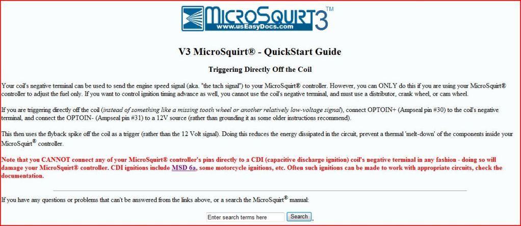
In the V3 Microsquirt EFI Controller Quick Start Guide the documentation specifically says that the gray/black wire to pin #31, the OPTOIN- "This pin must be connected to ground when feeding a square wave input signal to OPTOIN+ (pin 30)."
Here's the page I'm referencing: http://www.useasydocs.com/details/wire.htm
In fact, the description for properly connecting the gray/red wire for pin #30 also includes the direction that you should connect pin #31's wire to ground.
Am I missing something or misinterpreting the directions? We do agree that the diode and resistor circuit you're using creates a square wave output, right? So what am I not understanding about this situation?
Re: No "tach" signal
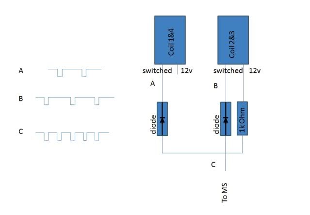
We're talking about wiring this circuit (pictured down below), right? So where it says "switched" it means that you splice into the coil's negative line which is still connected to the bike's ignition control box. And the 1K ohm resistor is connected to a switched 12 volt power source. And where it says "To MS" means to connect it to the gray/red OPTOIN+ wire.
Not shown is what to do with the gray/black OPTOIN- wire. The reason I believe it should be connected to ground is that the diode and resistor circuit is designed to send a mild current through the Microsquirt's OPTO isolator circuit (creating the upper limit of the square wave as drawn below) until one of the two coils is triggered by the bike's ignition box. When the bike's ignition box triggers either coil it grounds the line that our circuit's diode line is spliced into (creating the drop to ground of the square wave as drawn below).
So if all that is true and the gray/black OPTOIN- isn't wired to ground but is instead wired to 12volt power the square wave can never drop to ground and trigger the Microsquirt's OPTO isolator circuit.
Re: No "tach" signal
Ewflyer: Yep that is the circuitry I have now. I have tried this with the option grey/black to ground and then the grey/black to a 12 volt supply with no signal either way. The option grey/red is connected to the above circuit.
I originally had the option grey/red hooked up to one of the coils signal side (some may say negative, but it actually has 12 volts all the time and is dumped to ground to collapse the coil)...the other option grey/black was hooked to 12 volts as per this information:
Please excuse my ignorance..my background is mechanics..new to electronics...but I/we will figure this out.
The square wave signal I have now peaks at 11.5 volts and has a 10 signals every second while cranking. I'm not sure of the engines cranking speed at this moment, but it should show something on the screen?
I sincerely appreciate your help.
:Clifford
Re: No "tach" signal
I'm in the same boat. When it comes to electronics I try to carefully work from one "known" to another "known" in hopes of reaching a working solution.Please excuse my ignorance..my background is mechanics..new to electronics...
The thing that really surprises me here is that you mentioned this is your third Honda 4-cylinder conversion. It seems strange that you're running into trouble on this one. Are they all the same model?
But it sounds like you have some good information here:
So you're saying that when you hook the output of the diode and resister circuit to an oscilloscope you're getting a nice square wave-form on the screen? I'm guessing your motorcycle has two coils working in wasted spark mode to fire its four cylinders, right? That means the diode and resister circuit is getting an "event" every 180 degrees of crankshaft rotation. To get 10 signals per second your starter would have to be turning the crank at about 300 RPM (10 signals divided by 2 signals for every full crankshaft rotation equals 5 rotations per second times 60 seconds equals 300 RPM).The square wave signal I have now peaks at 11.5 volts and has a 10 signals every second while cranking.
I'm guessing the reason you got 11.5 volts during that test was because that was your battery's current state of charge.
If you've got a good square wave signal you have to be really close to a solution. You've checked to make sure your diodes are oriented correctly? With their banded ends pointed toward the coils?
Re: No "tach" signal
Ewflyer; Success!!! I'm not sure what happened...I sent the MS2 basic code into the controller and I now have an excellent tach signal. I had to recalibrate some of the sensors of course and I actually got the engine to fire a few times...'til the battery got low. So next chance I get, after work, I can start tuning...wooo hooo....
Note; I still am using the two diodes and single resistor attached to both coils and the option + (grey/red) connected to this. The option- (grey/black) is going to ground as you suggested. I am super pumped!!!
Thank you my friend for keeping me on track............
:Clifford
I'm going to tease you!!!
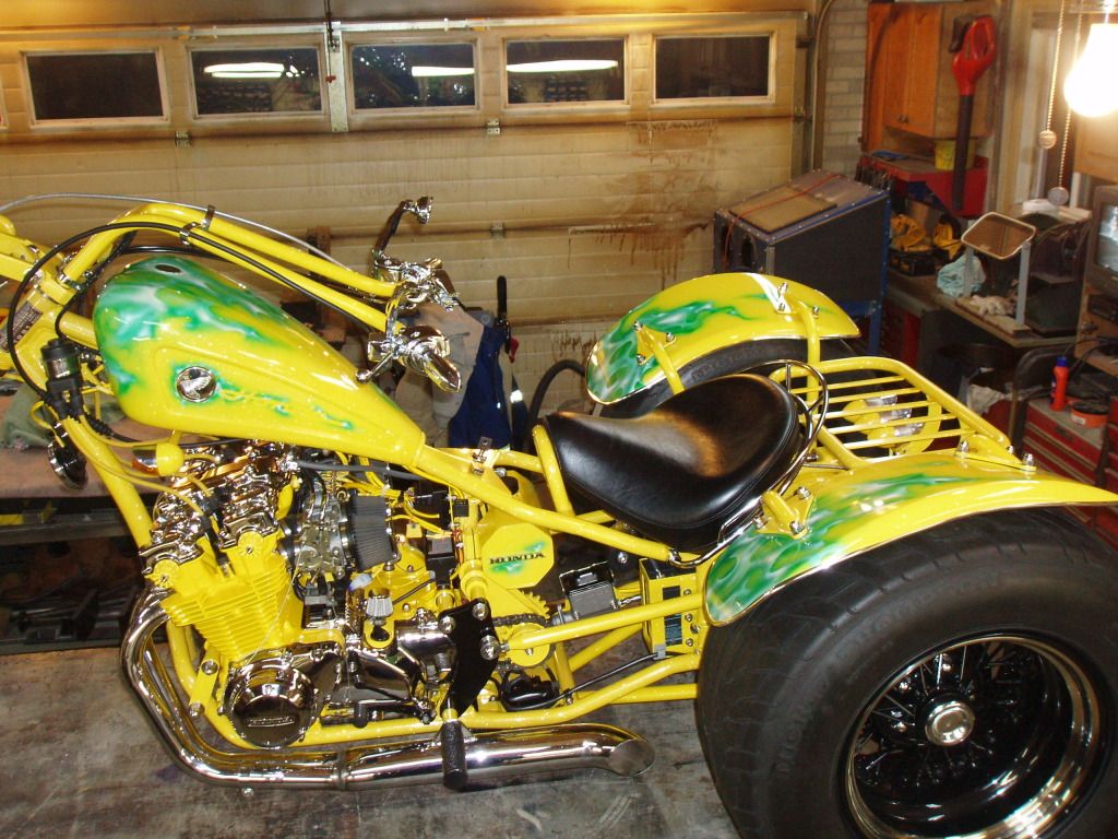
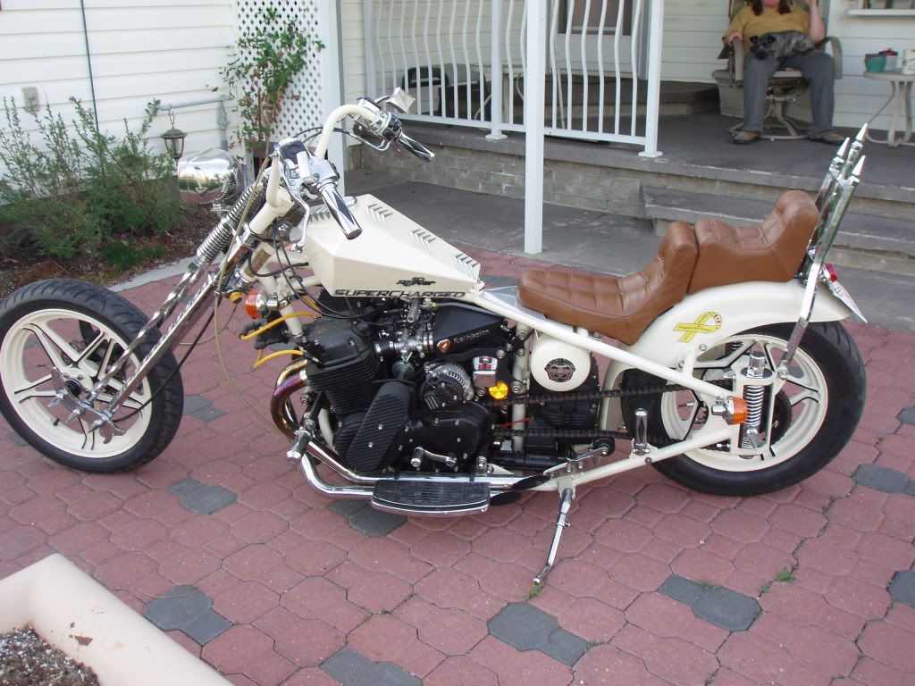
This is the old honda I'm working on now:
This was the very first fuelly:
This is the one I finished last year:
Note; I still am using the two diodes and single resistor attached to both coils and the option + (grey/red) connected to this. The option- (grey/black) is going to ground as you suggested. I am super pumped!!!
Thank you my friend for keeping me on track............
:Clifford
I'm going to tease you!!!
This is the old honda I'm working on now:
This was the very first fuelly:
This is the one I finished last year:
Re: No "tach" signal
Wow, nice pictures. That is some meticulous work you've done there. It appears you can do it all: engines, forced induction, paint, welding, all types of fabrication, etc.
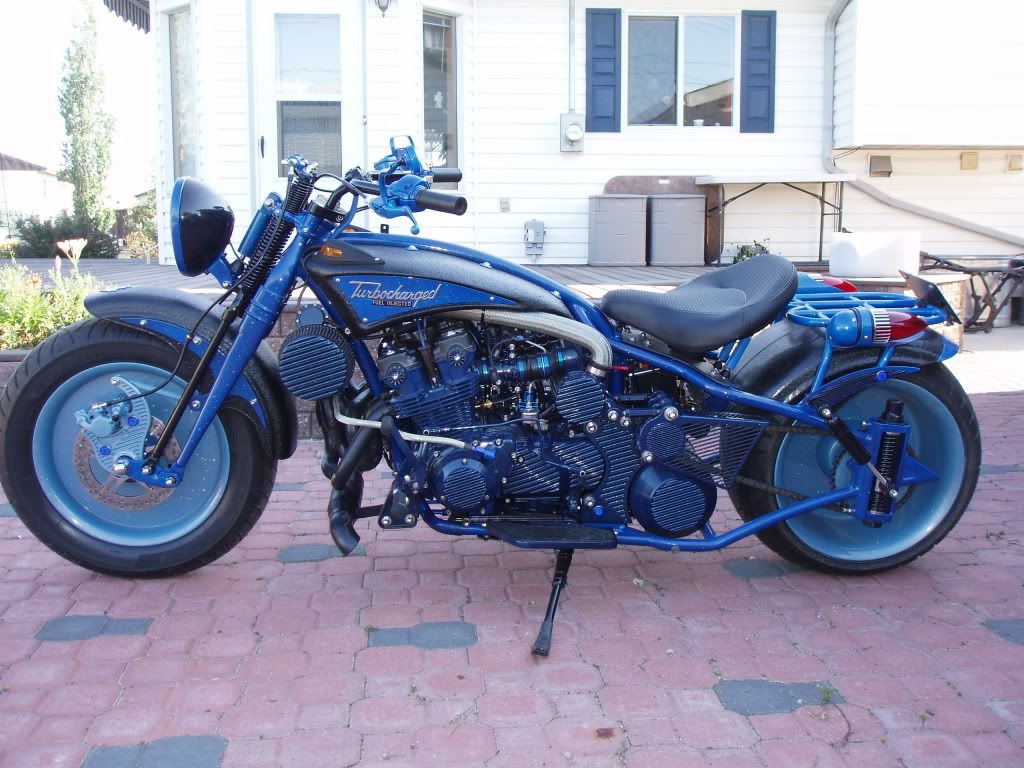
The blue bike is absolutely brutal looking. I'm pretty sure the white bike's engine is a CB750. What are the other two?
The blue bike is absolutely brutal looking. I'm pretty sure the white bike's engine is a CB750. What are the other two?
Re: No "tach" signal
Ewflyer; Thanks. The yellow trike is a 1981 Honda CB900, the Blue bike is a 1983 Honda CB750, and the White bike is a 1977 Honda CB750A.
Just ran into another problem!!! I started to tune and found my cranking RPM's were about 800? I removed the diodes and resistor...connected the option+ right to just one of the coils "switched" side with a 100 ohm resistor in-line...the option- is still going to ground. My cranking RPM is reading normal now (around 350-400)!! This fuel injection stuff sure does teach one to have patience...lol
Just ran into another problem!!! I started to tune and found my cranking RPM's were about 800? I removed the diodes and resistor...connected the option+ right to just one of the coils "switched" side with a 100 ohm resistor in-line...the option- is still going to ground. My cranking RPM is reading normal now (around 350-400)!! This fuel injection stuff sure does teach one to have patience...lol