IAC stepper recovery

For discussing injector selection, manifold modifications, throttle bodies, fuel supply system design and construction, and FIdle valves and IACs.
Forum rules
Read the manual to see if your question is answered there before posting. If you have questions about MS1/Extra or MS2/Extra or other non-B&G code configuration or tuning, please post them at http://www.msextra.com The full forum rules are here: Forum Rules, be sure to read them all regularly.
Post Reply
Noos95
MegaSquirt Newbie
Posts: 5
Joined: Sat Aug 03, 2013 4:25 am
Location: France

IAC stepper recovery

Post by Noos95 »

Hello There.

I’m Stefan from Rikus-automove.
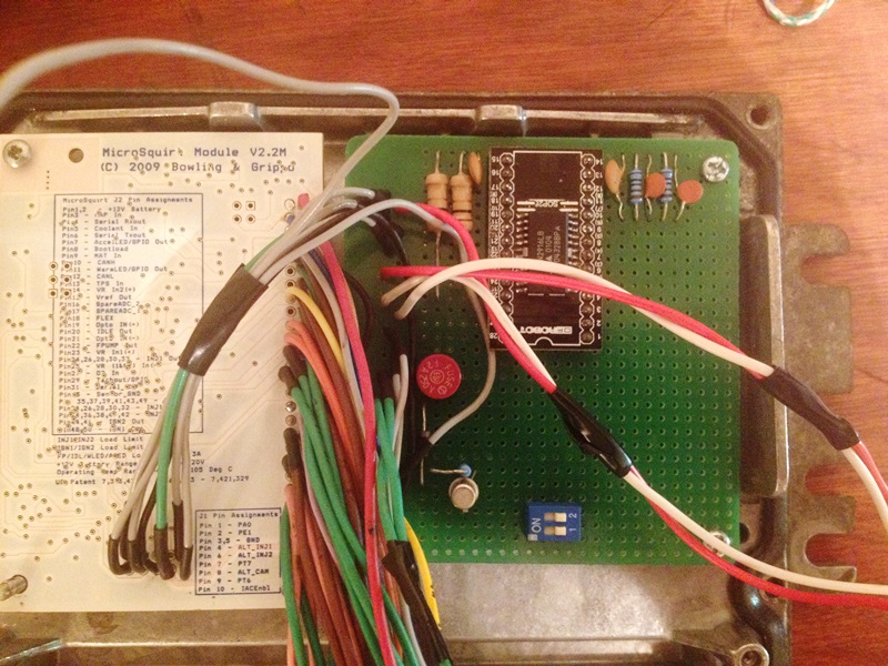
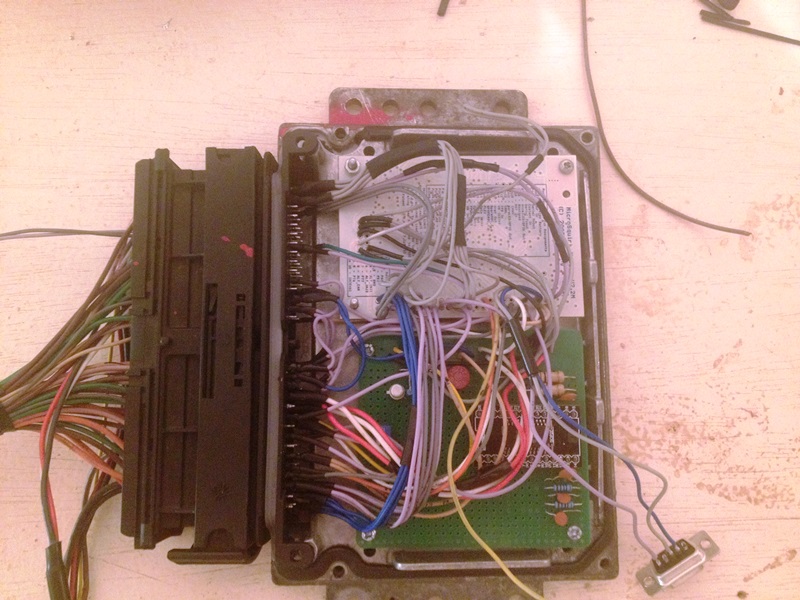
And I am using a microsquirt modul board 2.2 (case too small for an MS2) to build a PNP megasquirt for a French car.
That car is equipped (offcourse :) ) with an iac steper motor idle valve . I’m well aware that hardware (stepper micro controller) was remove from microsquirt ….

My plan is to build an addon board using PT6/PT7/iac enable from the microsquirt.
I’m a car enthusiast and an industrial electrician but I’m not an electronic specialist.

Image

Following the drawing from the MS2 I think it is strait forward
I have found supply of the microcontroller chip UDN2916LB
I will reproduce the set up from the MS2 board and wire PT6/PT7/IAC enable the same way.
I just need the confirmation of the resistor and capacitor I need to buy on the drawing.

R8/R7= 1 kilo ohm resistor?
C16 = 0.56 Farad ???? not milli or micro ?
C15/C13 = 0.1 Farad ???? not milli or micro ?
C14= 0.58 Farad ??? not milli or micro ?
R5/R6 = 1 Ohm 1 watt ????

Then I’ll build up the circuit and connect the processor and motor stepper controler

Iac Enble to Iac Enble
Pt6 to IAC1
Pt7 to IAC2
Vcc = what 5 volts ? from V ref ?


My last question is About the code.

I guess the code is unchanged and following the same steps than for a ms2 I can enable the stepper control

Thank you for you help
dontz125
Master Squirter
Posts: 375
Joined: Mon Jun 29, 2009 1:00 pm
Contact:

Re: IAC stepper recovery

Post by dontz125 »

Hi, Stefan.

Your values for the resistors are correct. The capacitor values are all in microfarads. This is common in electronics - if you don't see a unit for the capacitor, assume uF. The schematic is hard to read, but C14 and C16 are both 0.056 uF.

Vcc = 5v, and can be supplied from VRef.

I'll let someone else comment on the base code, but with MS2/Extra, you have to specify whether you are using a MegaSquirt2, a MicroSquirt, or a MicroSquirt Module - a lot of the pins are different. Once the correct model is specified, the module and MS2 work the same.
Noos95
MegaSquirt Newbie
Posts: 5
Joined: Sat Aug 03, 2013 4:25 am
Location: France

Re: IAC stepper recovery

Post by Noos95 »

dontz125 wrote:Hi, Stefan.

Your values for the resistors are correct. The capacitor values are all in microfarads. This is common in electronics - if you don't see a unit for the capacitor, assume uF. The schematic is hard to read, but C14 and C16 are both 0.056 uF.

Vcc = 5v, and can be supplied from VRef.

I'll let someone else comment on the base code, but with MS2/Extra, you have to specify whether you are using a MegaSquirt2, a MicroSquirt, or a MicroSquirt Module - a lot of the pins are different. Once the correct model is specified, the module and MS2 work the same.

Thank you for your help and answers :P

So. if it work the same and that the code is basicly the same except for the pin output. it should work without problem hahaha in theories. :mrgreen:

I guess this mod will please many members as I have seen the question flying around about how to use the stepper motor with a module.

I'm suppose to receive my resistors and capa during next week so 'ill keep you updated.
Noos95
MegaSquirt Newbie
Posts: 5
Joined: Sat Aug 03, 2013 4:25 am
Location: France

Re: IAC stepper recovery

Post by Noos95 »

IT WORKS!!!!!

He he , After a lot of month... where I did not have the time I finally completed my circuitry , incorporated the modul and my add on board inside a SAGEM 32 ECU enclosure and it works.....

when I test it with tuner studio watch channel is switching from +12v to -12v at the correct number of steps...

so I'm happy :mrgreen:
Noos95
MegaSquirt Newbie
Posts: 5
Joined: Sat Aug 03, 2013 4:25 am
Location: France

Re: IAC stepper recovery

Post by Noos95 »

I will post pics if i can get them out of my Fxxxing Iphone :yeah!:
Noos95
MegaSquirt Newbie
Posts: 5
Joined: Sat Aug 03, 2013 4:25 am
Location: France

Re: IAC stepper recovery

Post by Noos95 »

Hey ! the promise photos of the prototype build of an extension card to activate options on Microsquirt. mostly usfull for IAC stepper driver....

- First is the assembly of the stepper driver onto an adapter board to go from SOIC/SOP to DIL/DIP28

Image

Image

Image

Image

On a proto board , I have installed remaining components for IAC stepper set up as well as Boot load, general purpose output using PAO and later on (not on pics) install a "low activated input for dual table using PE1.

Image

Image

The making of tracks and connections.

Image

Image

Tested all inside a Sagem sirius 32n case and fited perfectly

Image

and finaly wiring up....

Image

Image

Image

Image

Image

Installed latest ms-extra firmware 3.3 I think.....

IAC control is sweatttttt and working, PAO additional output is working, but I get no responce on the BENCH( PC power supply not stim) for the dual table switch input (i have check setting and wiring and card) a the same for lauch control on neither of the inputs.... i beileive for launch control that it could be because no RPM detection on bench but i dont understand for the dual table, i would be directed to beleive that it should work and activate on bench regardless of engine running or not...

Anyhow that out of subject is this forum's section...

Waiting to test all on the car, I designed a finalised PCB using Kicad to have a final result looking OEM.

I will revise it a bit but design, functionalities, easy build up and reduced size are my criteria...

Current 3D view of the design....

Image

it is now 3" x 2.5" very compact.....

Please forgive the 3D render software that did not have the exact component like the DIP switch witch was replace with a DiP 4 type chip.
Rafaeldaf
MegaSquirt Newbie
Posts: 2
Joined: Thu Mar 02, 2017 9:40 pm
Location: America
Contact:

IAC stepper recovery

Post by Rafaeldaf »

Once you set the idle speed with the IAC disconnected youre supposed to plug it back in. If it runs wonky after plugged back in, something is up.

Youre not running the 10K resistor in your ALDL cable, are you?
Post Reply