Grounding on MicroSquirt

Forum for discussing how to install MicroSquirt(TM), choose and troubleshoot sensors, wiring, and communications for MicroSquirt (TM) and MicroSquirt Module(TM).
Forum rules
Read the manual to see if your question is answered there before posting. If you have questions about MS1/Extra or MS2/Extra or other non-B&G code configuration or tuning, please post them at http://www.msextra.com The full forum rules are here: Forum Rules, be sure to read them all regularly.
Bruce Bowling
Site Admin
Posts: 285
Joined: Mon Feb 16, 2004 4:25 pm
Location: Baltimore, MD

Grounding on MicroSquirt

Post by Bruce Bowling »

When running the grounds on MicroSquirt, it is important to remember that there are different "types" of grounds, which are:

1) High power grounds - these are the returns for the fuel injector and ignition drivers, and the fuel pump/fast idle/spare output drivers. There are three wires on the connectors for these, going to pins 21, 22, and 23 on the AMPSEAL - these are for the high power ground path. All three (3) of these wires need to ground direct to the engine block. It is important to run all three wires because it will reduce both the resistance and the overall inductance of the ground return path. Each wire has a resistance, and using three of them in parallel reduces the overall resistance. Equally important, each wire has an inductance, and inductances do not "like" fast-changing signals (like a pulse from a spark) and can cause very brief voltage offsets in the ground path. By having multiple wires it is the same as having multiple inductors in parallel, resulting in an overall lower inductance.

At the point on the engine block where the grounds hook together, it is a good idea to run a separate wire from this junction back to the battery as well. This is redundant, however it often cleans up noise from sources like the starter motor. And, if it does help then you should take another look at your big positive and negative wire on the battery...

Since we are talking battery - the point where you pick up the +12V to power the MicroSquirt is very important. This will go thru a relay in order to turn on and off the MicroSquirt, and the power source for the +12V on the relay needs to go back to the battery, or a path that leads direct to the battery without a long run of wiring. Just like for the grounds, I recommend running a separate wire from the relay direct back to the battery just to be sure.

To illustrate the grounding on the MicroSquirt, here is a picture of the ground plane layer of the board:

Image

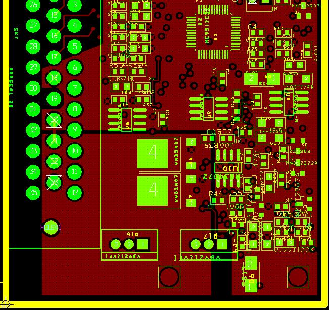
The red square on the lower left is the ground plane for the high current drivers. Note how this is separate from the other red ground plane above and to the right, which is the low current plane.

2) Sensor ground - the coolant sensor, intake air temperature sensor, throttle position sensor, and external MAP sensor needs to be grounded back to pin 18 on the AMPSEAL. This is the low-current sensor return path and it needs to be kept away from the high power ground. This wire hooks directly to the sensors only and not to the engine block - it is its own return path.

3) VR return ground - there is a separate VR(-) input on the AMPSEAL, this needs to be connected to the VR sensor(s). If you are using two VR sensors, return both back to this wire (these are low current and can be shared on the one wire retrun path) Do not ground the VR sensor anywhere else, return the ground back to the VR(-) terminal. On the MicroSquirt, this return goes directly back to the VR input circuit's transistor/op amp and not to the ground plane, this keeps the high amplitude VR voltages (and resulting currents) isolated to the VR circuit.

4) Serial return - the serial cable on the MicroSquirt has a separate ground return path thru the AMPSEAL connector. This return goes direct to the RS-232 transceiver (and not thru the ground plane, keeping the noise off...).

With the small size of MicroSquirt, keeping the grounds straight is important. It is not hard, just keep things in logical groups - high power stuff goes to engine block, sensors on their own ground loop, and the VR sensor is also separate.

To help visualize the ground paths for the high power drivers and the sensors, I have generated a "Mickey Mouse(R)" drawing of the current paths:

Image

The bottom of the image is the high power path, showing one ignition coil as an example. The current path is from the battery to the ignition coil to the MicroSquirt driver and back - see the light blue arrow path marking. The same goes on for the injector and general purpose outputs. Lots of juice flowing on this path, it needs to stay away from the sensors. It also needs a low resistance/inductance loop - you can see that the battery plays an important part of the path...

Speaking of the sensors, on the top of the image is the sensor return path. The Vref is the reference voltage generated by MicroSquirt, it passes thru the sensors and the return ground path comes back to the MicroSquirt. Only one return path is required for the sensors because it is comparatively low current, and we all know that voltage drop across a wire is driven by Ohm's law...

Finally, it is wise to dress the wires such that the high current "stuff" stays away from the sensor/VR/serial wires. Remember that an ignition coil flyback pulse is 350 volts with a current of 7 amps or so, a nice ElectroMagnetic Pulse (EMP) generator! If this gets into the sensors, VR, or serial connections then you will get all sorts of weird stuff going on...

- Bruce
diztroy
MegaSquirt Newbie
Posts: 7
Joined: Fri Jun 22, 2007 9:33 am

Re: Grounding on MicroSquirt

Post by diztroy »

Bruce Bowling wrote:
2) Sensor ground - the coolant sensor, intake air temperature sensor, throttle position sensor, and external MAP sensor needs to be grounded back to pin 18 on the AMPSEAL. This is the low-current sensor return path and it needs to be kept away from the high power ground. This wire hooks directly to the sensors only and not to the engine block - it is its own return path.
Bruce,

Thank you for the post above; all very helpful and informative! I have a question that relates to your second grounding point, specifically the coolant sensor ground.

The stock setup on my motorcycle is a one wire sensor to drive the temperature gauge. I was planing to use the stock sensor, but after reading your post I'm now having second thoughts. So from what your saying this will cause the low current sensor to be connected in a current path with high power components.

It will be somewhat difficult because the space on my motorcycle is at a premium, but would I be better off installing a 2-wire sensor that can be grounded to pin 18 the AMPSEAL?

-Troy
Bruce Bowling
Site Admin
Posts: 285
Joined: Mon Feb 16, 2004 4:25 pm
Location: Baltimore, MD

Re: Grounding on MicroSquirt

Post by Bruce Bowling »

diztroy wrote: The stock setup on my motorcycle is a one wire sensor to drive the temperature gauge. I was planing to use the stock sensor, but after reading your post I'm now having second thoughts. So from what your saying this will cause the low current sensor to be connected in a current path with high power components.

It will be somewhat difficult because the space on my motorcycle is at a premium, but would I be better off installing a 2-wire sensor that can be grounded to pin 18 the AMPSEAL?

-Troy
Yes, a lot of the temp sensors designed for gauge use have one end grounded to the threads for contact in the engine block. This is fine for gauge work, but for EFI you will notice that the majority of the sensors have two terminals (and insulated from the case/thread) such that a separate ground can be implemented. It is for this exact reason you indicate - to eliminate the possibility of an erroneous ground path.

It really would be best to go grab a GM sensor and install it, it will make life easier in the long run...

- Bruce
diztroy
MegaSquirt Newbie
Posts: 7
Joined: Fri Jun 22, 2007 9:33 am

Re: Grounding on MicroSquirt

Post by diztroy »

Bruce Bowling wrote:
It really would be best to go grab a GM sensor and install it, it will make life easier in the long run...
- Bruce
Done and done! My life is hard enough as it is :lol: Thank you for clearing that up. -Troy
Richard0327
MegaSquirt Newbie
Posts: 8
Joined: Fri Mar 25, 2005 5:27 pm
Location: Jaffrey, NH, 03452, USA

Re: Grounding on MicroSquirt

Post by Richard0327 »

Hi Bruce:
Have a question! I have been having grounding problems with the Black board MicroSquirt and as I was looking through this publication of yours of 3 years ago about grounding, I am confused. The reason I am confused is because it states and I quote "Sensor ground - the coolant sensor, intake air temperature sensor, throttle position sensor, and external MAP sensor needs to be grounded back to pin 18 on the AMPSEAL." All that is OK except the pin#. In the docs I have been using "MicroSquirt wiring" this pin is #20 not 18. In the docs pin #18 is labeled N/C (ground). I wouldn't even have taken a second look except that the board you are displaying on the page is just like mine. Please let me know which pin it is. Thanks again.
Bruce Bowling
Site Admin
Posts: 285
Joined: Mon Feb 16, 2004 4:25 pm
Location: Baltimore, MD

Re: Grounding on MicroSquirt

Post by Bruce Bowling »

Richard0327 wrote:Hi Bruce:
Have a question! I have been having grounding problems with the Black board MicroSquirt and as I was looking through this publication of yours of 3 years ago about grounding, I am confused. The reason I am confused is because it states and I quote "Sensor ground - the coolant sensor, intake air temperature sensor, throttle position sensor, and external MAP sensor needs to be grounded back to pin 18 on the AMPSEAL." All that is OK except the pin#. In the docs I have been using "MicroSquirt wiring" this pin is #20 not 18. In the docs pin #18 is labeled N/C (ground). I wouldn't even have taken a second look except that the board you are displaying on the page is just like mine. Please let me know which pin it is. Thanks again.
Actually, it can be either pin 18 or pin 20 for the sensor ground. Look at the top image of the groundplane, you will see that both pin 18 and pin 20 (the one with the hourglass symbol on it) contact the upper ground plane, so technically you can use either pin for the sensor ground - either will work equally well.

- Bruce
clcorbin
MegaSquirt Newbie
Posts: 2
Joined: Mon Jan 17, 2011 3:46 pm
Location: Albuquerque, New Mexico

Re: Grounding on MicroSquirt

Post by clcorbin »

Bruce Bowling wrote: Actually, it can be either pin 18 or pin 20 for the sensor ground. Look at the top image of the groundplane, you will see that both pin 18 and pin 20 (the one with the hourglass symbol on it) contact the upper ground plane, so technically you can use either pin for the sensor ground - either will work equally well.

- Bruce
Looking at the pin out chart, it shows pin 18 is N/C (no connection I assume) but is labeled as "Secondary Sensor Ground". From that and your statement above, I would have to assume that both pin 18 and pin 20 can be used interchangeably or both used (say for different sensors). Quick (and probably trivial) question for you: why was it labeled N/C in the first place?
Regards,

Clint
750steve

Re: Grounding on MicroSquirt

Post by 750steve »

In the case of LS2 Truck coils the 12v in, main earth, Microsquirt 5v signal & ground are beside each other, is this a problem for EMI/RFI ?
Matt Cramer
Super Squirter
Posts: 910
Joined: Sat Jul 03, 2004 11:35 am

Re: Grounding on MicroSquirt

Post by Matt Cramer »

750steve wrote:In the case of LS2 Truck coils the 12v in, main earth, Microsquirt 5v signal & ground are beside each other, is this a problem for EMI/RFI ?
Not really. The spark plug wires are the potential EMI / RFI source.

Note that for things that are running on 12 volts, there's very few things that generate enough EMI / RFI to be a problem. The real problem is things injecting noise into the 12 volt plane.
Matt Cramer at DIY Autotune
Image
750steve

Re: Grounding on MicroSquirt

Post by 750steve »

Thank you Matt.

On my Microsquirt i've noticed there are only 2 high power ground wires (solid black & thick), has there been a change since the wiring since the Microsquirt Wiring page was published, it mentions 3 black wires
Post Reply